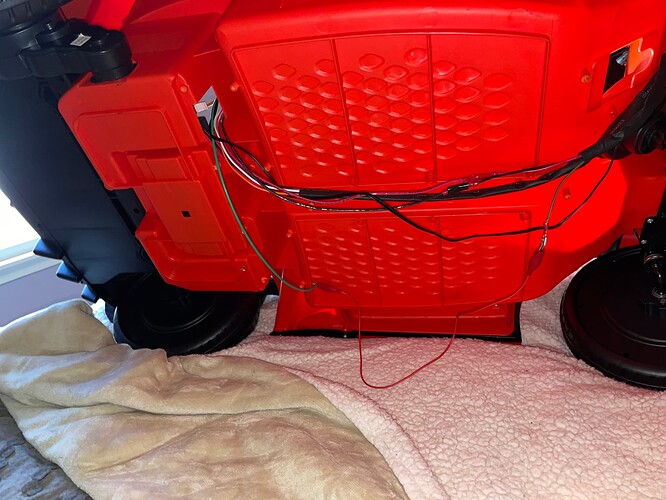
We are using a big red button switch, and we cannot get the car to go. We are using a relay, but need some assistance for wiring to determine what we are doing wrong. Any help is greatly appreciated!
if you could post some pictures i / we will have a better chance of figuring it out. happy to help if possible
When you press the Big Red button switch, can you hear the relay click? This will help us determine whether the problem is "in front of the relay " or “behind” it.
Hi all!! I am adding some photos for reference. We took the wiring apart just so it is easier for you to see where everything would connect. Underneath there are two different sets of wires. The black, red, and white ones go to the dashboard and battery. A white and orange one go to the dashboard and the motor. A green/brown, white, and red go to the dashboard and the pedal. I labeled the wires on the inside of the car.
We do not hear a click
Thank you, that helps a lot. I apologize for the next request, but I can’t see what I need to in the pictures. Could you please take a closeup of the relay with the highest resolution your camera or phone has? We now need to see the pins on the relay and which wires are connected to which pins. The pictures I am getting on this web page are too fuzzy when I try to look for details. Another option would be to directly email me the new pictures as attachments in case they are somehow being compressed via the posting here. Does this make sense?
Doug,
We are using a SARL-112DF relay. I can definitely email you pictures if that would be easier!
Well, that relay should work for what you are trying to do. Let’s do both – post the pictures of the relay and its connections here, and then email them to me, too. I need to be able to read the numbers off the relay pins. They should be something like 30, 85, 86, 87, etc. and I need to see which wires go to each pin. The reason for continuing to post here is so Pete and others can help. The reason for emailing them is so I can see if that improves the detail. Are you working from a drawing or instructions on how to wire the relay in? If so, could you please send those along since there are several ways to do this? Also, do you have access to a multi-meter and know how to use it to measure voltage?.
Below are the directions we are following. I got them from GoBabyGo - Riley : 8 Steps - Instructables
"For ease of use, we removed the pedal in the floorboard which moved the car, and added a Big Red Button.
However, this complicates things, as we don’t want the full power going across the Big Red Button, so we’re going to use a Relay. We chose the SARL- 112DF, with the wiring diagram pictured.
To power the coil of the relay, we’re going to tap into the battery power and run it through the big button to power the relay, and then from the relay to the battery ground. To simplify things, we’ll use the hot wire coming off of the emergency stop switch we installed earlier.
To activate the car, we’ll just use the wires from the pedal we removed to actually start the car. You can see from the picture that the pedal was just a simple switch that connected two leads. These leads are what we’re going to run across the N/O and common connectors. Make sure that 1) you use the normally open connection on the relay, and 2) you connect the “hot” wire to the lead marked 87 (not 87a).
You can identify the hot wire by turning on the car, and reading the voltage between each wire and ground. The one that shows 12V is the hot wire. (above, the brown wire with the electrical tape is the hot wire from the pedal; the brown wire without the electrical tape is the not-hot wire from the pedal)
We opted to use quick disconnects on the wires going to the steering wheel so that we could run them easily through the chassis, but it’s not required.
We installed the relay itself underneath the seat, with the other electronics and battery. Since the relay had a mounting hole on one side, we drilled a small hole in the side wall of the car’s chassis, and connected it with a bolt and nut."

OK, thank you, this is commonly used approach and since it requires you to measure voltage I assume you have the multi-meter and know how to use it. When you have a chance to send me the picture of the wires attached to your relay so I can look at which pins they go to, we can decide what to do next. Since you do not hear the relay click we will probably look first at pins 85 and 86.


